Design and Operation of a Hydrogen Supply Chain
Increasing oil prices make it more rewarding to look for alternative energy sources to fuel future propulsion.
In the case of the reviewed paper today I selected one of a few papers I recently discovered on this topic. If you like to know more just let me know.The basic assumption of this paper sets hydrogen as the replacement energy storage for oil.
Oil availability peak
Expert opinions diverge on how long oil based energy reserves might last, but even energy companies only admit another 70 years. That sounds like a lot of time… But the implementation of a hydrogen supply chain, which differs to a great extend from current processes also would take decades.
Problem / Model
The authors focus their model on the hydrogen demand for transportation vehicles only. Other aspects where energy/hydrogen might be needed are not considered. The problem can be defined as follows:
The hydrogen supply chain of interest consists of: medium-to-large centralized hydrogen production facilities, transportation modes and large-scale storage facilities. We assume that hydrogen may be produced from three different energy sources: natural gas (methane), coal and biomass via two distinct types of commercially proven technologies, namely steam methane reforming and gasification. The purified hydrogen generated from the central facility has to either be liquefied or compressed before being stored or distributed. Liquid hydrogen is stored in super-insulated spherical tanks to minimize heat loss and boil-off rate, then delivered via tanker trucks or railway tank cars. In contrast, compressed-gaseous hydrogen is stored in pressurized cylindrical vessels to increase the energy density, and distributed by tube trailers or railway tube cars. The different types of storage facilities would be located either next to the production facilities or away from the production source serving as distribution terminals.
The model focusses on three strategic decisions to fulfill customer needs:
- number,
- location and
- type and capacity of hydrogen production plants and storage facilities.
Three scenarios for the configuration are analyzed:
- Distribution of liquid hydrogen with railway and truck-transportation to various storage facilities,
- Distribution of the hydrogen in compressed form, and
- Distribution only by tanker trucks.
The authors apply their model to the case of Great Britain and use this as a basis to estimate the demand level for transportation purposes.
Based on these assumptions the authors develop a mixed-integer linear program.
The objective function is based on the facility capital and operating cost:
The aim of the proposed model is to minimise both capital and operating costs of the hydrogen supply chain. The former are one-time costs associated with the establishment of production plants, storage facilities, and transportation links. On the other hand, operating costs are incurred on a daily basis and are associated with the cost of production of hydrogen at the plants, the cost of their storage, and the cost of their transportation through the network. Although a variety of metrics could be investigated in a more detailed study, such as well-to-wheel analysis of CO2 emissions, we focus on cost here.
Results
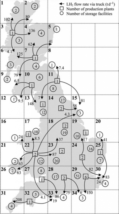
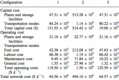
Figure 1 shows the selected optimal design of the supply chain for Great Britain. And figure 2 lists the overall costs.

Figure 1: Scenario 3: Optimal Network Structure (Almansoori and Shah, 2006)

Figure 2: Cost of the Hydrogen Network in three Cases (Almansoori and Shah, 2006)
The authors conclude:
The model and assumptions presented in this paper reveal that the optimum future hydrogen supply chain might consist of medium-to-large, centralized methane steam reforming plants. The hydrogen produced from these plants will then be delivered as a liquid via tanker trucks and stored in centralized storage facilities.
Conclusions
The authors already mention some weaknesses of the proposed model. The focus is on the simulation of a future state of the network, any pre-existing facilities and capabilities are basically ignored and on these grounds the “best” model is selected. But the current state might influence the future network. Also the authors do not cover how the future network should be developed and which parts should be established first.
Also, one has to note that the difference between the cost of scenarios 1 and 3 (figure 2) are quite low, the authors still decide against an additional distribution via railway: “This is because it is more favourable to use tanker trucks instead of railway tank cars for transporting liquid hydrogen due to the flexibility in operations.”
An assumption which I find questionable at least: A mixed transportation should usually combine the aspects of flexibility of a road transportation and the cost advantages of rail transport.
Almansoori, A., & Shah, N. (2009). Design and operation of a future hydrogen supply chain: Multi-period model International Journal of Hydrogen Energy, 34 (19), 7883-7897 DOI: 10.1016/j.ijhydene.2009.07.109


Add new comment